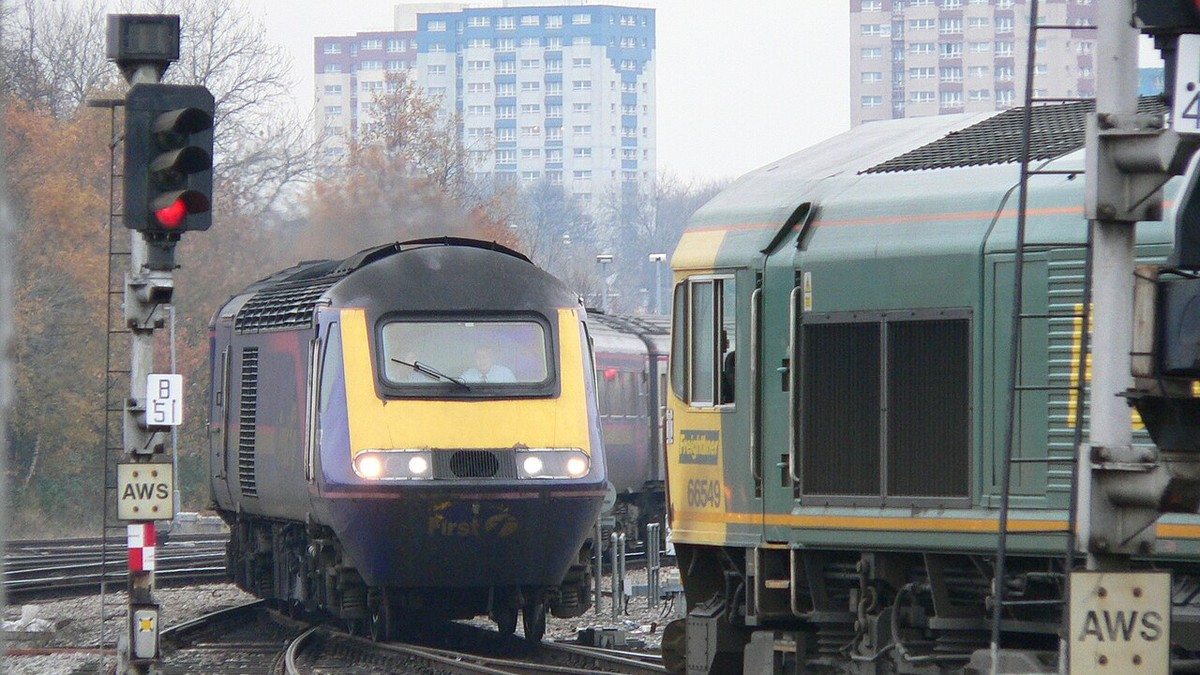
Railway operations are fundamentally governed by a terrifying physical reality: a heavy train traveling at speed cannot steer around obstacles, and its braking distance vastly exceeds the visual sighting distance of the locomotive driver. In the dawn of the railway era, this geometric constraint led to horrifying rear-end and head-on collisions. To establish safe train separation, electrical engineers and railway telegraphers created the discipline of railway signalling. From primitive visual ball signals and time-interval dispatching to the electromagnetic Absolute Block system, mechanical interlocking frames, electric token instruments, and continuous track circuits, signalling transformed railways into the safest mass transit systems on earth.
🚂 The Fatal Flaw of the Time-Interval System
Prior to the 1850s, railways operated under the Time-Interval System: after a train departed a station, no subsequent train was permitted to follow until a fixed interval (typically 5 to 10 minutes) had elapsed. The fatal flaw was blindingly obvious: if the preceding train suffered a mechanical breakdown, boiler failure, or axle fracture just around a blind curve, the following train, running at full speed under a clear time interval, slammed into its rear, causing catastrophic carnage.
1. Primitive Visual Communication and the Semaphore Revolution
The earliest railway signalling was entirely visual, delegated to railway policemen—frequently retired military officers wearing top hats and red coats—stationed at milepost intervals along the right-of-way. Using their arms or colored flags, policemen gave hand signals: arm extended horizontally for Danger (Stop), arm held at 45 degrees for Caution, and arm held vertically or by the side for Clear (All Right).
In the United States, early lines deployed the Ball Signal: a physical canvas-covered globe hoisted to the top of a high timber mast via a rope and pulley. If the ball was hoisted to the high masthead, the track was clear—giving rise to the immortal American railroading term highballing (running at full authorized line speed). Conversely, if the ball was lowered, danger was indicated.
In 1841, Scottish civil engineer Sir Charles Hutton Gregory introduced the Semaphore Signal to the London and Croydon Railway at New Cross. Borrowed from Chappe’s optical military telegraph, the semaphore featured an elevated timber mast supporting a pivoted horizontal blade or arm. A horizontal arm indicated Danger; an arm lowered to 45 degrees indicated Caution; and an arm dropped into a vertical slot inside the post indicated Clear. Colored glass spectacles (red for danger, green or white for clear) moved across an oil lamp lens at night, providing uniform optical signals in darkness. Gregorys semaphore became the universal visual language of global railways for over a century.
| Signalling Era / Technology | Invention Period | Operating Philosophy | Limiting Vulnerability / Failure Mode |
|---|---|---|---|
| Policemen & Hand Flags | 1825 – 1845 | Time-Interval separation; manual visual signaling. | Fog blindness; human inattention; zero detection of broken-down trains. |
| Mechanical Semaphores | 1841 – 1860s | Standardized arm angles and colored night spectacles. | Lacked physical interlocking with track switches; signalman memory errors. |
| Absolute Block System | 1850s – 1870s | Space-Interval separation; single train per block section. | Depended on telegraph wire communication between signal boxes. |
| Saxe & Farmer Interlocking | 1856 – 1870s | Mechanical locking dogs; impossible to set conflicting routes. | Physical cable stretch; limited lever frame mechanical reach. |
| Electric Token / Tablet | 1878 – 1880s | Single-line physical key token interlock (Tyer/Webb). | Manual token exchange required at speed; token pouch misses. |
| DC Track Circuit (Robinson) | 1872 – Present | Continuous failsafe electrical train detection via rails. | Broken rail detection; automated signal control; basis of modern cab signals. |
2. The Absolute Block System and the Space-Interval Principle
The catastrophic shortcomings of time-interval separation spurred the development of the Space-Interval Principle, universally formalized as the Absolute Block System.
Under Absolute Block regulations, the entire railway mainline is partitioned into discrete geographical segments called Block Sections, flanked at each end by a manned signal box (signal tower). The fundamental, unbreakable golden rule of the Absolute Block is absolute: No train shall ever be permitted to enter a block section until the signalman at the exit end has officially verified and transmitted telegraphic confirmation that the preceding train has completely vacated the section, passed his home signal, and is proceeding under clear authority.
To coordinate train movements, signal boxes were linked by dedicated electromagnetic needle telegraphs and block bell instruments. Signalmen communicated via standardized bell codes (e.g., 3-1 for Call Attention, 4 consecutive beats for Is Line Clear for Express Passenger Train). By substituting absolute physical space for unreliable time intervals, rear-end collisions were virtually eliminated across double-track mainlines.
3. Mechanical Interlocking: Saxby & Farmer’s Mechanical Brain
While the Absolute Block secured open-line running, busy railway junctions—where multiple tracks crossed, converged, and diverged—remained death traps. If a signalman pulled the wrong lever, clearing a green signal while a turnout switch was set against an oncoming train, a catastrophic collision was inevitable.
In 1856, English inventor John Saxby patented the Mechanical Interlocking Lever Frame, subsequently perfected alongside John Stinson Farmer as the renowned Saxby & Farmer Interlocking System. Saxby recognized that the levers controlling track switches and the levers controlling optical signals must be bound together by a rigid, mechanical logic.
Beneath the lever floor of the signal box, Saxby installed an intricate matrix of horizontal sliding bars (tappets) and pivoted steel wedges (dogs) housed within a heavy cast-iron locking bed. When a signalman grasped the catch-handle of a lever, the motion of the spring latch drove a tappet through the locking bed before the main lever could physically move. If the route was conflicting, steel dogs mechanically deadlocked the lever, making it physically impossible for human muscle to pull the lever. To clear a signal for a main-line express, the signalman was mathematically compelled to set and lock every switch point in the correct alignment first. Saxby and Farmers mechanical computer eliminated human memory lapse from railway junctions.
🚂 The Clayton Tunnel Disaster (1861)
On August 25, 1861, inside the long, smoke-filled Clayton Tunnel on the London, Brighton and South Coast Railway, three heavily laden excursion trains entered the bore within minutes of each other under a botched time-interval and manual telegraph scheme. When the second train stalled inside the dark tunnel, a confused signalman mistakenly signaled the third train into the bore, resulting in a horrific telescoping collision that killed 23 passengers and injured 176. The disaster shocked Victorian society and led Parliament to pass the landmark Regulation of Railways Act 1889, which legally mandated the compulsory installation of the Absolute Block system, mechanical interlocking, and continuous automatic brakes on all passenger railways in Great Britain.
4. Single-Line Token Working: Tyers Tablets and the Webb-Thompson Staff
Operating single-track railways presented a terrifying operational hazard: the risk of head-on cornfield meets between trains traveling in opposite directions. To prevent two opposing trains from occupying the same single-track section, railways instituted the Token System.
The philosophical premise was elegant: the physical possession of a tangible token—such as a heavy wooden staff or brass tablet—served as the sole legal authority for a locomotive driver to enter the single-line section. Because only one unique token existed for the entire section, two trains could never collide.
However, a simple wooden staff was operationally rigid: if three westbound trains were scheduled to run before an eastbound train arrived, the staff was trapped at the wrong end of the section. In 1878, Edward Tyer patented the Electric Tablet System, followed in 1888 by F.W. Webb and A.M. Thompson of the London and North Western Railway with the Electric Train Staff Instrument.
Under the Webb-Thompson system, two identical cast-iron pillar instruments were installed in the signal boxes at opposite ends of the single-track section, electrically connected by a single telegraph wire. Each instrument contained a magazine of heavy brass staffs with unique annular collars. Through electromagnetic galvanometers and polarity-reversing commutator drums, the two machines were locked in continuous electromagnetic equilibrium. A staff could be extracted from either machine—but the moment one staff was withdrawn, both machines locked down completely, preventing the extraction of any other staff until the first staff was physically inserted into the instrument at the other end. Single-line safety was guaranteed by the laws of electromagnetism.
5. William Robinson and the Closed DC Track Circuit (1872)
All early signalling systems suffered from a shared vulnerability: they relied on human signalmen to visually verify that a train had fully cleared a section. In dense fog, blizzards, or pitch-black nights, a signalman could easily overlook a detached rear carriage sitting silently on the mainline.
In August 1872, American electrical engineer William Robinson patented the Closed DC Track Circuit—the most brilliant, foundational invention in the entire history of railway automation. Robinson recognized that the steel running rails of the railway track bed could be utilized as electrical conductors.
The track circuit was engineered as a continuous, fail-safe electrical loop:
- The running rails were divided into electrically isolated track blocks by inserting insulated joints (fiber or composite shims) between rail ends.
- At one end of the block, a low-voltage battery (typically 1.5 to 2.0 volts DC) was connected across the two rails.
- At the opposite end of the block, an electromagnetic relay coil was connected across the rails, energized continuously by current flowing through the steel rails.
- While the block was empty, the relay remained energized, holding a heavy magnetic armature closed, which illuminated a green signal.
- The moment a train entered the block, its massive steel wheels and solid steel axles formed a path of virtually zero electrical resistance, short-circuiting the battery current across the wheelset before it reached the relay. De-energized, the relay armature dropped by gravity, instantly switching the signal to red.
The genius of Robinsons closed track circuit was its absolute fail-safe architecture. If a battery failed, if a wire severed, if a rail cracked completely in half, or if lightning struck, the relay automatically de-energized, dropping the signal to its most restrictive indication (Red). The train carried its own protection with it wherever it rolled.
6. Modern Signalling: Cab Signalling, CBTC, and ERTMS/ETCS
As train velocities scaled past 125 mph on twentieth-century passenger corridors, line-side optical semaphore and color-light signals reached their human operational limits: a driver hurtling through heavy fog at 180 mph has barely two seconds to observe and react to a wayside green or yellow aspect.
Modern high-speed rail networks have replaced lineside signals with automated In-Cab Signalling and Train Protection Systems. Technologies such as Frances TVM-430 (deployed on TGV lines) and Germanys LZB transmit continuous digital speed codes directly through coded track circuits and inductive cable loops into the drivers cab display.
Today, the global standard is the European Rail Traffic Management System / European Train Control System (ERTMS/ETCS). Under ETCS Level 2 and Level 3, trains communicate continuously with lineside Radio Block Centres (RBC) via secure GSM-R digital radio telemetry. Fixed block sections are replaced by dynamic Moving Blocks: computerized safety zones that move continuously with the train, calculated in real-time based upon the trains instantaneous velocity, mass, and braking curve. If a driver fails to obey braking curves, automated Automatic Train Protection (ATP) computers override the human controls and execute emergency service braking. Through two centuries of relentless technical evolution, railway signalling has evolved from hand flags waved by Victorian policemen into an invisible, fail-safe digital matrix that safely transports billions of passengers every year.
Track Circuit Electrical Physics and Fail-Safe Interlocking Logic
The safety of modern railway transport is governed by the absolute fail-safe principle: any electrical power outage, mechanical breakage, wire severance, or component degradation must instantly cause signalling devices to revert to their most restrictive state (‘Danger’ / Red stop indication). In the earliest decades of railway operations, trains were separated solely by ‘Time Interval Working’. A policeman or signalman permitted a train to depart, displayed a ‘Danger’ flag for five minutes, a ‘Caution’ flag for an additional five minutes, and then gave an ‘All Clear’ signal, assuming the preceding train had progressed miles ahead. If a train stalled or broke an axle around a blind curve, the following train slammed into its rear at full speed, causing horrific catastrophes such as the Clayton Tunnel disaster of 1861.
The salvation of railway signalling emerged from two monumental electrical and mechanical inventions: the Closed Track Circuit, invented by American engineer Dr. William Robinson in 1872, and Mechanical Interlocking, patented by British engineer John Saxby in 1856. Robinson recognized that early open-circuit designs (which energized a relay only when a train completed a circuit) were fatally flawed because a broken wire, dead battery, or corroded rail gave a false ‘Clear’ indication. Robinson inverted the logic to create the DC Closed Track Circuit.
🚂 Robinson’s Closed Track Circuit: The Electrical Physics of Rail Safety
A low-voltage DC battery (1 to 2 volts) is connected across the two running rails at one end of a track block, insulated from adjacent sections by nylon-insulated rail joints. At the opposite end of the block, a sensitive electromagnetic track relay is connected across the rails, held in an energized, picked-up position by the continuous trickling current. When a train enters the block, the steel wheelsets act as a low-resistance electrical shunt across the rails. The current bypasses the relay coil, de-energizing the relay and causing its heavy gravity-loaded armature to drop, immediately breaking the green lamp circuit and illuminating the red ‘Stop’ signal.
Crucially, if a rail cracks completely in two, a battery fails, or a feeder cable is cut by maintenance crews, current flow ceases instantly, the relay drops, and the signal automatically displays ‘Danger’. This fail-safe architecture remains the gold standard of world railway safety.
Simultaneously, Saxby’s mechanical interlocking machine resolved human operator error in signal boxes. In a busy junction, throwing a points switch while an conflicting signal showed ‘Clear’ resulted in disastrous side collisions. Saxby connected all switch levers and signal levers to an intricate grid of reciprocating locking bars, dogs, and tappets inside a mechanical locking bed. When a signalman pulled the lever to set a route, the sliding tappet physically locked the levers of all conflicting signals in the ‘Danger’ position, making it mechanically impossible for a signalman to clear conflicting movements.
| Signalling Era / Technology | Time Period | Train Separation Basis | Primary Failure Mode / Vulnerability |
|---|---|---|---|
| Time Interval Working | 1825–1850s | Arbitrary clock time (5–10 min intervals) | Catastrophic rear-end collisions if lead train stalled |
| Absolute Block Working | 1850s–1900s | Space interval; telegraph block instruments | Human operator error in telegraph code transmission |
| Closed DC Track Circuit (Robinson) | 1872–Present | Continuous electrical detection via wheelset shunt | Occasional wheel-rail rust film impedance; broken insulated joints |
| Automatic Block Signalling (ABS) | 1900s–1970s | Color-light multi-aspect signals (Red/Yellow/Green) | Driver signal passed at danger (SPAD) in blinding fog |
| Cab Signalling & ETCS / PTC | 1990s–Present | Digital radio balises; continuous in-cab target braking | Software sensor errors; GPS multipath signal dropouts |
Modern railway signalling has evolved from mechanical locking frames and copper telegraph wires to European Train Control System (ETCS Level 2 and Level 3) and American Positive Train Control (PTC). Transponders (balises) embedded in the track bed transmit digital speed envelopes directly to on-board locomotive computers. If an engineer fails to brake for a curve or red signal, the fail-safe computer overrides human control and applies full emergency brakes, ensuring zero collisions across high-density rail corridors.