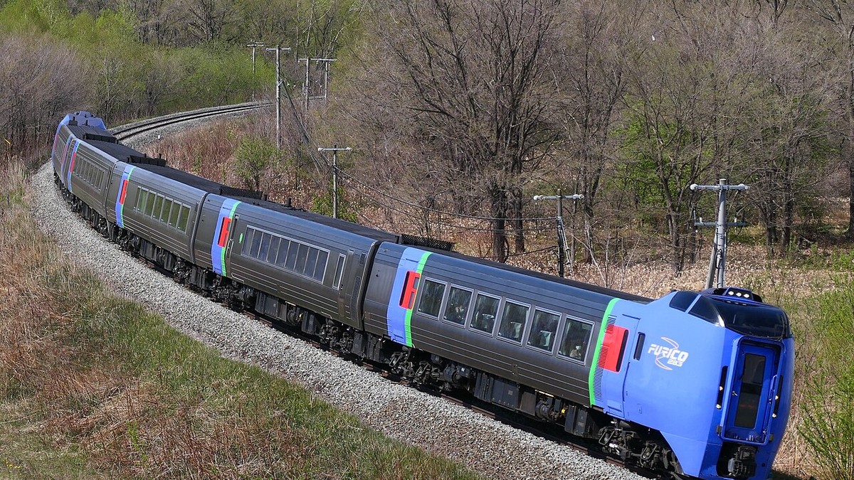
The physics of guided terrestrial locomotion is dictated by precision track geometry. Unlike an automobile whose driver steers actively across an open roadway, a railway vehicle is guided entirely through the passive kinematic contact between its coned steel wheel treads and the steel railhead profile. As train speeds scale from nineteenth-century 30-mph branchlines to modern 200-mph high-speed corridors, track alignment geometry becomes an exacting science of Newtonian mechanics. From the mathematics of clothoid transition spirals and equilibrium cant (superelevation) to Nadals derailment quotient (L/V), precision track geometry is the invisible bulwark of railway safety.
🚂 The Conicity Principle: Passive Self-Centering Kinematics
A fundamental mechanical discovery of early railroading was wheel-tread conicity. Train wheels are not cylindrical; they are conical, possessing a bevel (typically 1:20 or 1:40) that slopes inward toward the flange. When a wheelset shifts laterally on a curve, the outer wheel rolls on a larger effective rolling diameter than the inner wheel. This automatically generates a differential rolling radius that steers the wheelset around the curve without the flange ever making abrasive contact with the railhead under normal operational conditions.
1. Cant (Superelevation) Physics and Centrifugal Force Neutralization
When a train traverses a horizontal curve of radius R at velocity v, passengers and rolling stock experience a lateral centrifugal acceleration directed radially outward: a = v^2 / R.
Left uncorrected, this lateral force imposes severe discomfort upon passengers, shifts cargo loads, and forces the wheel flanges against the outer running rail, creating intense friction, abrasive flange wear, and risk of catastrophic wheel climb.
To neutralize centrifugal acceleration, civil engineers apply cant or superelevation (Ea): the outer rail of the curve is elevated above the inner rail by a calculated vertical height. By canting the track plane at an angle relative to horizontal, the normal reaction force of the track bed is tilted inward, decomposing gravity into an inward component that directly opposes the outward centrifugal thrust.
Theoretical Equilibrium Cant occurs when the inward gravitational component precisely balances the outward centrifugal force, resulting in zero net lateral acceleration on passengers and identical vertical axle load distribution across both the inner and outer rails: Equilibrium Cant = (Track Gauge times Velocity squared) divided by (Gravity times Radius).
| Geometric Parameter | Mathematical Symbol | Standard Gauge Limit (Freight) | High-Speed Rail Limit (Passenger) |
|---|---|---|---|
| Maximum Applied Cant (Superelevation) | Ea | 140 – 150 mm | 160 – 180 mm |
| Maximum Cant Deficiency (Underbalance) | Dc | 75 – 100 mm | 130 – 150 mm (Tilting Trains: 250 mm) |
| Maximum Cant Excess (Overbalance) | Eex | 90 – 110 mm | 70 mm (Avoids slow freight inner rail crush) |
| Rate of Cant Transition Slope | dE / dL | 1:400 to 1:600 | 1:1000 to 1:1500 (Minimizes twist jerk) |
| Lateral Track Acceleration Limit | ay | 0.05 g (0.5 m/s²) | 0.10 g (1.0 m/s²) Passenger Comfort |
2. Cant Deficiency vs. Cant Excess: The Mixed-Traffic Dilemma
Achieving pure equilibrium cant is straightforward on dedicated single-purpose tracks, such as high-speed lines where every train runs at identical speeds. However, the vast majority of global railway infrastructure operates as mixed-traffic corridors, carrying 30-mph heavy mineral freight trains and 100-mph passenger expresses over the exact same tracks.
This introduces an acute engineering compromise between cant deficiency and cant excess:
- Cant Deficiency (Underbalance): Experienced by fast passenger trains traveling above equilibrium speed. The applied cant is insufficient to fully cancel centrifugal force; passengers feel a gentle outward pull, and the outer rail experiences higher dynamic vertical and lateral loading.
- Cant Excess (Overbalance): Experienced by slow, heavy freight trains dragging up steep mountain grades below equilibrium speed. The inward tilt is excessive; gravity pulls the train heavily down onto the low (inner) rail. If cant excess exceeds 110 mm, 32-ton freight axles will literally crush and mushroom the inner railhead, accelerating rolling contact fatigue and corrugation.
Civil engineering standards mandate strict upper thresholds for cant deficiency and excess. To permit higher passenger speeds through curves without exceeding passenger comfort limits, specialized tilting trains (such as the Italian Pendolino, British Class 390, and Swedish X2000) deploy hydraulic or electromechanical carbody tilting actuators that bank the passenger compartment an additional 6 to 8 degrees inwards, allowing the train to negotiate curves with up to 250 mm of cant deficiency without inducing passenger motion sickness.
3. Transition Spirals: The Clothoid and the Elimination of Centrifugal Shock
In primitive early track construction, straight tangent track connected directly to circular curves. This geometric layout was lethal: upon crossing the tangent-to-curve boundary, the radius abruptly collapsed from infinity to R, and lateral acceleration leaped from zero to v^2/R in zero seconds. This instantaneous surge in lateral force imposed a violent mechanical jerk that battered the rolling stock, threw passengers from their seats, and caused frequent derailments.
To eliminate centrifugal shock, modern railway geometry mandates the insertion of a transition spiral (clothoid or Euler spiral) between straight tangent track and circular curves.
Along a clothoid transition curve, the curvature increases linearly with arc length from zero at the tangent point to the full curve radius at the curve point. Simultaneously, superelevation is introduced gradually along the transition as a uniform vertical ramp. As a consequence, lateral acceleration and cant rise in continuous mathematical synchrony, ensuring that the rate of change of lateral acceleration (jerk, measured in m/s³) remains smoothly within human comfort limits (typically 0.3 m/s³ or lower).
🚂 Nadals Formula: The Mechanics of Wheel Climb Derailment
The most terrifying failure mode in track geometry is wheel climb: the flange of a heavily loaded wheel rides upward over the railhead corner and jumps the track. In 1908, French engineer M. J. Nadal formulated the critical derailment quotient: (Lateral Force / Vertical Load) must not exceed (tan delta – mu) / (1 + mu tan delta). Where delta is the contact angle of the wheel flange (typically 68° to 75°), and mu is the friction coefficient. If dynamic track twist reduces vertical load while curve resistance elevates lateral load, the ratio breaches Nadals safety limit (approx. 0.8 to 1.2), causing instantaneous wheel climb.
4. Gradient Compensation on Curves
When a train negotiates a grade on a curve, it confronts two simultaneous sources of tractive resistance: gravitational grade resistance (20 lbs/ton per 1% grade) and curve resistance (0.8 lbs/ton per degree of curvature) caused by flange rubbing and wheel slip.
If a railway alignment maintains an unadjusted ruling grade of 1.5% through both straight tangents and tight 8-degree curves, the total tractive resistance encountered by a freight locomotive climbs to the equivalent of a 2.1% grade on the curves, causing the train to stall or slip its drivers.
To maintain uniform tractive demand across mountain divisions, civil engineers practice gradient compensation: the actual physical gradient is systematically flattened throughout curved sections according to standard compensation formulas: Compensated Grade = Ruling Grade minus (0.04 times Degree of Curvature). On an 8-degree curve along a 1.5% ruling corridor, the physical grade is reduced to 1.18%, guaranteeing that an engine working at maximum tractive effort can haul its rated tonnage across curves without stalling.
5. Track Irregularities and Dynamic Track Twist Failures
Track geometry is continuously degraded by repetitive axle passes and ballast settlement, generating four primary dimensional errors:
- Gauge Variation: Widening or narrowing of the transverse distance between railheads, risking wheelset drop-in or gauge jamming.
- Vertical Profile (Top): Longitudinal dips and humps in the running surface that induce vertical pitch-and-bounce resonance in rail vehicles.
- Alignment (Line): Lateral sinusoidal wanderings from true tangent alignment, inducing severe vehicle hunting oscillations.
- Track Twist: The most lethal defect, representing the spatial rate of change of cross-level between two points separated by the wheelbase of a bogie (typically 3 meters). If the left rail dips sharply while the right rail rises, the diagonal wheel of a four-wheel bogie is partially unloaded, collapsing vertical force and triggering instantaneous wheel-climb derailment under Nadals equation.
6. High-Speed Alignments and Global Standards
Modern high-speed rail networks represent the absolute pinnacle of precision geometric design. On lines engineered for 300 to 350 km/h (186 to 217 mph) operations—such as the French TGV LGV lines, Japanese Shinkansen, and Chinese CRH corridors—horizontal curve radii are massive, rarely dropping below 5,000 to 7,000 meters.
At these vast radii, superelevation is maintained at a modest 120 to 140 mm, transition spirals extend for over 600 meters in length, and track vertical crest curves feature radii exceeding 25,000 meters to eliminate any sensation of weightlessness or vertical g-force surge. Track geometry tolerances are enforced through millimeter-scale automated slab-track systems, in which rails are fastened directly onto precision-cast reinforced concrete roadbeds anchored into bedrock, completely eliminating the shifting settlement of ballast. Through the continuous synthesis of Newtonian dynamics, metallurgy, and automated geodesy, track geometry remains the quiet, invisible science that ensures trains glide across continents with unparalleled safety, efficiency, and speed.
Transition Spirals, Clothoid Mathematics, and Derailment Dynamic Physics
The geometric design of railway permanent way represents an intricate branch of applied classical mechanics. When a train traveling at velocity v enters a circular curve of radius R, the vehicle mass m is subjected to an outward centrifugal acceleration equal to \( a_c = rac{v^2}{R} \). If left uncompensated, this lateral acceleration produces severe passenger discomfort, causes uneven wear on the gauge face of the outer rail, and generates a dynamic overturning moment that can induce catastrophic flange climbing derailments.
To neutralize centrifugal acceleration, civil engineers elevate the outer rail above the inner rail by a height E, termed superelevation or ‘cant’. By tilting the track plane inward at an angle θ, the resultant vector of the gravitational force \( m \cdot g \) and the centrifugal force acts perpendicularly to the axle plane, eliminating lateral shear on the wheels. The theoretical equilibrium cant E is expressed by the formula:
E = rac{G \cdot v^2}{g \cdot R}
where G is the effective track gauge distance between rail centers (approximately 1,500 mm for standard gauge), g is gravitational acceleration (9.81 m/s²), v is train speed in meters per second, and R is curve radius in meters.
🚂 Nadal’s Derailment Criterion: The Physics of Flange Climb
When wheelsets negotiate tight track curves, the wheel flange contacts the gauge face of the outer rail at an angle. French engineer M. J. Nadal formulated the fundamental mathematical limit governing whether the wheel will slip safely or climb over the railhead: \( rac{L}{V} \le rac{ an \delta – \mu}{1 + \mu an \delta} \), where L is lateral wheel force, V is vertical wheel load, δ is the wheel flange contact angle (typically 68° to 75°), and μ is the wheel-rail friction coefficient. If the ratio \( rac{L}{V} \) exceeds approximately 0.8 to 1.2, flange climbing derailment occurs instantaneously.
Because passenger trains and heavy freight trains share the same track at vastly different speeds, track cannot be canted for the highest speed without causing slow, heavy freight trains to grind against the low inner rail. Engineers resolve this conflict by designing track for a compromise speed and allowing ‘cant deficiency’ (under-elevation for high-speed trains) or ‘cant excess’ (over-elevation for slow freight trains). High-speed tilting trains (such as the Italian Pendolino or Swedish X2000) actively tilt the passenger coach body by up to 8 degrees on curves, compensating for cant deficiency without modifying the fixed track bed.
Furthermore, a train cannot transition instantly from a straight tangent track (zero cant, infinite radius) into a circular curve (full cant, constant radius) without inducing severe lateral jerk (\( rac{da}{dt} \)) that would derail the train. Track designers insert a mathematical transition curve—specifically a clothoid (Euler spiral) or cubic parabola—between tangent and circular curves. Along the transition spiral, curvature increases linearly with distance while cant is gradually applied along a smooth vertical ramp, keeping lateral jerk strictly below 0.3 m/s³ for optimal passenger comfort and absolute structural safety.
| Geometric Parameter | Formula / Derivation | Standard Limit (High-Speed Line) | Civil Engineering Hazard if Exceeded |
|---|---|---|---|
| Equilibrium Cant (E) | E = (G * v²) / (g * R) | Max 160–180 mm (6.3–7.1 in) | Excess cant causes slow freight to crush inner rail |
| Cant Deficiency (D) | D = E_equilibrium – E_actual | Max 80–100 mm (Standard stock) | Passenger discomfort; high lateral wheel gauge wear |
| Transition Spiral Type | Clothoid (Curvature ∝ Arc Length) | Length L ≥ 0.007 * Cant * Speed | Abrupt curvature change triggers lateral wheel flange strike |
| Nadal Derailment Ratio | L/V Limit = (tan δ – μ) / (1 + μ tan δ) | Critical Threshold ≈ 0.8–1.0 | Flange climb derailment over the outer high rail |
| Gradient Compensation | G_comp = G_actual – (0.04 / R_curve) | Max ruling gradient 1.0% to 2.5% | Locomotive wheelslip & train stalling in curves |
Through rigorous mathematical calculation of cant gradients, transition spirals, and gradient compensation, modern permanent way civil engineering guarantees that trains weighing thousands of tons glide securely through high-speed curves with millimeter precision.