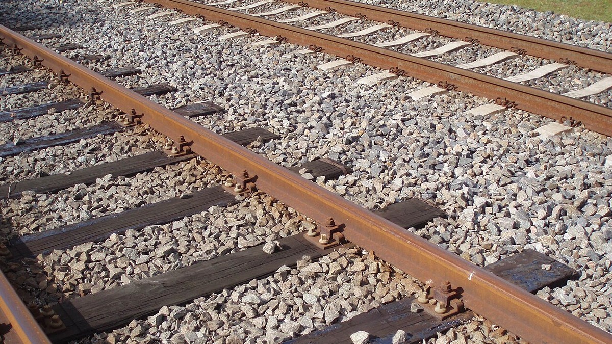
The permanent way—the foundational infrastructure comprising the formation subgrade, granular ballast, cross-ties (sleepers), fastenings, and running steel rails—represents the most critical civil engineering system in rail transport. Unlike highway pavements that distribute static axle loads broadly across sub-base soils, a railway track structure is an elastic beam on a resilient foundation, subjected to violent dynamic impact loadings, lateral centrifugal thrusts, and extreme thermal stresses. From nineteenth-century jointed fishplate tracks to modern pre-stressed concrete sleepers and flash-butt Continuous Welded Rail (CWR), the evolution of track engineering defines the limits of train speed, axle tonnage, and operational safety.
🚂 The Elastic Foundation Paradigm (Winkler-Zimmermann Model)
In railway geotechnics, track mechanics is governed by the Winkler-Zimmermann hypothesis: the rail is modeled as a continuously supported Euler-Bernoulli beam resting on an elastic subgrade characterized by a modulus of track elasticity (k). Every passing wheel flattens a localized deflection basin beneath it, creating cyclical bending stresses and dynamic wave propagation through the ballast matrix that must be absorbed without permanent subgrade deformation.
1. Subgrade Geotechnics and Drainage Mechanics
The ultimate structural integrity of any railway corridor depends entirely upon the stability of the subgrade—the natural soil formation or compacted earthwork upon which the track bed rests. Subgrade failures represent the most catastrophic and expensive maintenance emergencies in railway civil engineering.
When saturated with groundwater or surface runoff, fine-grained cohesive soils (such as silts and plastic clays) undergo shear failure under the pulsating dynamic pressures transmitted from passing axle loads. This induces subgrade pumping or mud pumping: cyclic wheel deflections generate high pore-water pressures that liquefy underlying clay slurries, forcing them upwards through the voids of the granular ballast. Once contaminated with fine silt, the ballast loses its inter-particle frictional interlock, resulting in localized track subsidence, line-and-level irregularities, and sudden speed restrictions.
Modern permanent-way engineers mitigate these geotechnical failure modes through sophisticated multi-layered drainage designs:
- Capping Layer (Sub-Ballast): A dense, well-graded layer of crushed stone, gravel, and sand (150 mm to 300 mm thick) possessing high permeability and structural stiffness. It acts as an impermeable umbrella, shedding water laterally toward cess drains while preventing upward clay migration.
- Non-Woven Geotextile Membranes: Engineered synthetic polymer fabrics placed between the subgrade and sub-ballast. These act as selective three-dimensional hydraulic filters that allow water to escape while permanently blocking fine soil particles.
- Continuous Deep Cess Drains: Perforated lateral drainage pipes backfilled with filter stone running along the track cess, maintaining the water table at least 1.5 meters below the bottom of the sleeper to eliminate frost heave and capillary saturation.
| Track Structure Layer | Typical Thickness | Primary Material | Mechanical Function in Track Matrix |
|---|---|---|---|
| Running Rail | 150 – 175 mm Profile | Pearlitic / Head-Hardened Carbon Steel | Direct wheel contact; beam load distribution; electrical signaling conduit. |
| Fastenings & Baseplates | 25 – 50 mm | Cast Steel / Resilient Spring Clips (Pandrol) | Clamps rail to tie; maintains gauge; provides electrical insulation. |
| Cross-Ties (Sleepers) | 150 – 200 mm | Creosoted Hardwood / Pre-Stressed Concrete | Maintains track gauge; transfers wheel load across ballast footprint. |
| Top Ballast | 250 – 350 mm | Crushed Angular Basalt / Granite (28–50 mm) | Resists lateral/longitudinal track creep; absorbs dynamic energy; instant drainage. |
| Sub-Ballast / Capping | 150 – 300 mm | Graded Sand & Crushed Aggregate | Spreads stress footprint onto soil; prevents mud pumping; waterproof shed. |
| Compacted Subgrade | Infinite (Native) | Compacted Clay / Silt / Bedrock Formation | Ultimate foundation bearing capacity; must maintain CBR > 8 for heavy tonnage. |
2. The Mechanics of Ballast: Angularity, Interlock, and Tamping
Railway ballast is far more than casual gravel poured around sleepers; it is a meticulously engineered granular skeleton that performs three indispensable functions: it resists lateral and longitudinal track displacement caused by thermal expansion and braking forces; it dissipates concentrated sleeper loads onto the capping layer; and it provides immediate, voided drainage for torrential rainfall.
Ideal ballast consists of tough, high-density, crushed angular stone—predominantly granite, basalt, quartzite, or hard dolomite—screened to tight particle size distributions between 28 mm and 50 mm. Rounded river gravel is strictly prohibited because smooth pebbles roll across each other like ball bearings under load, exhibiting zero lateral shear resistance. Under dynamic axle pounding, the sharp angular facets of crushed basalt interlock through micro-friction, creating a semi-rigid stone mattress.
Over time, continuous traffic breaks down the angular edges of the stone through mechanical attrition and abrasion, filling ballast voids with pulverized stone dust (ballast fouling). Once fouled, ballast cements together into an impermeable crust, trapping water and accelerating track deterioration. To restore track geometry, modern railways deploy automated on-track tamping machines (such as Plasser & Theurer dynamic tampers). These machines deploy vibrating squeeze tines that penetrate the ballast bed beneath each sleeper, fluidizing the stone with 35-Hz vibrations and consolidating it tightly beneath the rail seat, restoring track line, level, and cross-level within tolerances of a single millimeter.
3. Cross-Ties (Sleepers): Hardwood, Concrete, and Composite Evolution
The cross-tie serves as the structural spine of the track, maintaining exact track gauge (the transverse distance between railheads) while distributing wheel loads evenly across the ballast matrix.
For over a century, pressure-creosoted timber ties—predominantly oak, Douglas fir, jarrah, or beech—dominated global railways. Timber possesses outstanding natural resilience, excellent shock-absorption capabilities, and is easily worked and bored for spike insertion. However, wood is vulnerable to biological fungal rot, insect attack, mechanical spike-killing (enlargement of spike holes under dynamic lateral hunting), and plate-cutting under heavy axle loads. In wet or tropical environments, timber tie life expectancy drops to barely ten to fifteen years.
In the post-WWII era, pre-stressed concrete mono-block sleepers emerged as the global standard for heavy-haul freight and high-speed passenger lines. Fabricated from high-strength Portland cement concrete reinforced with high-tensile steel prestressing tendons under tension, concrete ties offer exceptional compressive strength and an operating lifespan exceeding fifty years. Crucially, a standard concrete tie weighs approximately 280 to 320 kg—more than triple the weight of an equivalent timber tie (80 to 100 kg). This colossal inertial mass anchors the track structure firmly against lateral thermal buckling, providing the absolute dimensional stability demanded by Continuous Welded Rail (CWR).
🚂 The Pandrol Resilient Fastening Revolution
In traditional track, rails were secured to timber ties with rigid cut spikes or cast-iron chairs with timber keys. Under high-speed vibration, rigid fastenings worked loose, causing gauge widening and rail overturn. In 1957, Norwegian railway engineer Per Pande-Rolfsen invented the Pandrol clip—a self-tensioning, heat-treated spring steel clip shaped like a figure-eight. Driven into a cast-iron shoulder embedded in the concrete sleeper, the Pandrol clip exerts a continuous, elastic toe clamping force of over 1.25 tons onto the rail foot, dampening high-frequency vibrations while preventing longitudinal rail slip under maximum braking.
4. From Jointed Track to Continuous Welded Rail (CWR)
For the first century of railway history, tracks were constructed from individual rail sections (typically 39, 45, or 60 feet in length) connected at their ends by pairs of steel splice plates called fishplates, secured by four or six heavy bolts. To accommodate the thermal expansion and contraction of the steel under ambient temperature fluctuations, a deliberate expansion gap (1/8 to 3/8 inch) was left between adjacent railheads.
While mechanically simple, the jointed rail was an operational and economic disaster. As each wheel rolled across the expansion gap, it dropped into the void and slammed into the receiving railhead, generating the rhythmic, romantic clickety-clack beloved of passengers—but despised by civil engineers. This repetitive impact battered the rail ends into mushroomed shapes, pulverized the underlying ballast, sheared fishbolts, and consumed over 50% of the entire railway maintenance budget.
The introduction of Continuous Welded Rail (CWR) in the 1950s revolutionized permanent-way engineering. CWR eliminates mechanical joints by welding standard rail lengths into continuous, unbroken ribbons of steel extending for miles, or across entire continents. Rail sections are joined in specialized automated depots using flash-butt electric resistance welding, while field closures are executed via the aluminothermic (thermite) process, which ignites iron oxide and aluminum powder to produce molten steel at 2,500°C that fuses the rail ends into a single homogeneous crystal structure.
5. Thermal Stress Management and Track Buckling Physics
The elimination of expansion gaps in CWR introduces colossal internal thermal forces. Steel possesses a linear thermal expansion coefficient of approximately 0.0000115 per degree Celsius. When constrained from physical expansion by heavy concrete sleepers, ballast shoulders, and resilient fastenings, any temperature deviation from the track installation state induces massive internal longitudinal stresses according to Hookes Law: Force = Elastic Modulus times Area times Thermal Coefficient times Temperature Delta.
For a standard 60 kg/m rail profile, every Celsius degree change induces longitudinal forces exceeding 1.7 to 2.0 tons per rail. On a scorching summer afternoon when direct solar radiation elevates rail steel temperatures to 55°C, a standard track panel experiences internal longitudinal compressive loads exceeding 100 tons per rail.
If the lateral resistance of the ballast bed is insufficient, this compressive stress will cause the track to buckle explosively into a sinusoidal sun kink, shifting the rails meters laterally in a split second and causing catastrophic derailments. To prevent buckling, modern railways practice rail stressing: rails are mechanically stretched with hydraulic pullers or artificially heated to a precise Stress-Free Temperature (SFT)—typically 27°C in the UK and 35°C to 40°C in warmer climates—before final neutral welding. In summer, the compressive forces remain safely below the lateral ballast resistance threshold; in winter, the tensile forces remain safely below the tensile fracture limit of the steel.
6. Modern Track Inspection and Automated Ultrasonic Telemetry
Ensuring the ongoing safety of high-speed passenger lines carrying trains at 200 mph and heavy freight corridors with 32-ton axle loadings demands non-destructive testing (NDT) technologies that operate continuously at mainline speeds.
Modern infrastructure authorities deploy specialized track recording vehicles (such as Network Rails New Measurement Train in Britain or Plasser EM-Series inspection cars). These high-speed test trains utilize optical laser profiling systems that scan the railhead geometry at 1,000 Hz, calculating track gauge, vertical alignment, cant, and twist with sub-millimeter precision.
Simultaneously, multichannel ultrasonic wheel transducers and high-definition eddy-current sensors probe the internal crystal matrix of the steel rails, detecting microscopic internal fatigue fissures—such as transverse fissures, vertical split heads, and rolling contact fatigue (RCF) head checks—long before they propagate to catastrophic rail fracture. Defective rail sections identified by telemetry are immediately tagged via GPS and replaced overnight by mechanized maintenance gangs, ensuring that the permanent way remains a resilient, frictionless, and secure foundation for global rail transport.
Continuous Welded Rail (CWR) Physics, Neutral Temperature, and Flash-Butt Welding
The transition of modern permanent way civil engineering from jointed track to Continuous Welded Rail (CWR) during the mid-twentieth century eliminated the destructive dynamic impact forces associated with traditional bolted rail joints. In jointed track, the 0.25-inch expansion gap between adjacent rail ends created the rhythmic ‘clickety-clack’ sound familiar to generations of passengers. However, each wheel impact over these gaps delivered high-frequency hammering shockwaves (up to 30 Gs of dynamic acceleration) that pulverized track ballast, sheared fishplate bolts, induced rail-end batter, and caused premature fatigue cracking along the rail bolt-holes.
Continuous Welded Rail resolves this vulnerability by welding standard 60-foot or 80-foot rolled rail strings into continuous ribbons extending for thousands of feet or miles. However, eliminating expansion joints introduces immense thermal stresses governed by Hooke’s Law of elasticity. A steel rail constrained against longitudinal expansion experiences thermal axial forces expressed by the formula:
F = E · A · α · ΔT
where E is Young’s modulus of rail steel (210 GPa), A is the cross-sectional area of the rail (approximately 77 cm² for standard UIC 60 / 136 RE rail), α is the coefficient of thermal expansion (1.15 x 10⁻⁵ per °C), and ΔT is the temperature change from the Rail Neutral Temperature (RNT). A temperature swing of 35°C (63°F) above the neutral temperature generates over 140 kilonewtons (31,500 lbf) of compressive longitudinal force in each rail. If the track superstructure lacks sufficient lateral resistance, this compressive force triggers catastrophic lateral track buckling (sun kinks), which instantly derails approaching trains.
🚂 The Rail Neutral Temperature (RNT) Stress-Free Protocol
To prevent both summer buckling (compression) and winter rail breaks (tensile fracture), track engineers destress CWR to a strictly calculated Rail Neutral Temperature (typically 27°C to 35°C / 85°F to 95°F, depending on local climate extremes). During installation, hydraulic rail tensors pull the steel strings to simulate the exact physical expansion corresponding to the target RNT before the rails are clamped into prestressed concrete sleepers using elastic spring clips (such as Pandrol e-Clips or Fastclips).
CWR ribbons are joined in the field using two primary metallurgical welding processes: mobile flash-butt welding and aluminothermic (thermite) welding. Flash-butt welding employs high-current electric arcs that heat the rail ends to forging temperatures (1,400°C) before hydraulic rams force them together under immense upsetting pressure, producing a forged crystalline bond with mechanical strength virtually indistinguishable from parent rolled rail. For in-situ field repairs and switches, aluminothermic welding uses an exothermic chemical reduction reaction between iron oxide and aluminum powder inside a refractory crucible:
Fe₂O₃ + 2 Al → Al₂O₃ + 2 Fe (liquid) + 851.5 kJ of thermal energy
The superheated molten steel (at over 2,500°C / 4,500°F) pours into a sand mold around the rail gap, fusing the rail ends into a seamless metallurgical joint that withstands millions of gross tons of heavy freight and high-speed passenger traffic.
| Permanent Way Component | Material Specification | Primary Structural Function | Failure Mode if Degraded |
|---|---|---|---|
| Running Rail (UIC 60 / 136 RE) | Pearlitic carbon steel (R260 / R350HT) | Supports wheel loads; guides wheelsets | Rolling contact fatigue (head checks, squats) |
| Fastening System (Pandrol / Vossloh) | Tempered spring steel clips & nylon pads | Clamps rail to sleeper; provides torsional resistance | Fatigue fracture; loss of toe load & gauge widening |
| Sleeper / Tie (B70 Concrete) | Prestressed high-strength concrete (60 MPa) | Maintains track gauge; transfers load to ballast | Center cracking; alkaline-silica reaction (ASR) |
| Track Ballast | Angular crushed granite / basalt (25–65 mm) | Provides vertical/lateral shear resistance; drains water | Ballast fouling; fine attrition; mud pumping |
| Subgrade / Formation | Compacted geotextile & crushed gravel sub-ballast | Ultimate load-bearing soil foundation | Differential settlement; shear failure & track dips |
Combined with modern laser-guided dynamic tamping machines and ballast regulators that maintain track geometric alignment to tolerances within fractions of a millimeter, continuous welded rail forms the indispensable civil engineering foundation supporting contemporary 200 mph bullet trains and 30,000-ton bulk freight consists worldwide.